Basic x86 interrupts
April 02, 2016
From my article on a multiboot kernel, we saw how to load a trivial kernel, print text and halt forever. However, to make it usable I want keyboard input, where things I type will be printed on the screen.
There is more work than you might initially think because it requires initialization of x86 interrupts: this quirky and tricky x86 routine of 40 years legacy.
x86 interrupts
Interrupts are events from devices to the CPU signalizing that device has something to tell, like user input on the keyboard or network packet arrival. Without interrupts you should’ve been polling all your peripherals, thus wasting CPU time, introducing latency and being a horrible person.
There are 3 sources or types of interrupts:
- Hardware interrupts - comes from hardware devices like keyboard or network card.
- Software interrupts - generated by the software
intinstruction. Before introducingSYSENTER/SYSEXITsystem calls invocation was implemented via the software interruptint $0x80. - Exceptions - generated by CPU itself in response to some error like “divide by zero” or “page fault”.
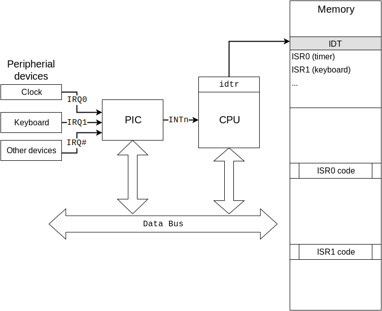
x86 interrupt system is tripartite in the sense of it involves 3 parts to work conjointly:
- Programmable Interrupt Controller (PIC) must be configured to receive interrupt requests (IRQs) from devices and send them to CPU.
- CPU must be configured to receive IRQs from PIC and invoke correct interrupt handler, via gate described in an Interrupt Descriptor Table (IDT).
- Operating system kernel must provide Interrupt Service Routines (ISRs) to handle interrupts and be ready to be preempted by an interrupt. It also must configure both PIC and CPU to enable interrupts.
Here is the reference figure, check it as you read through the article

Before proceeding to configure interrupts we must have GDT setup as we did before.
Programmable interrupt controller (PIC)
PIC is the piece of hardware that various peripheral devices are connected to instead of CPU. Being essentially a multiplexer/proxy, it saves CPU pins and provides several nice features:
- More interrupt lines via PIC chaining (2 PICs give 15 interrupt lines)
- Ability to mask particular interrupt line instead of all (
cli) - Interrupts queueing, i.e. order interrupts delivery to the CPU. When some interrupt is disabled, PIC queues it for later delivery instead of dropping.
Original IBM PCs had separate 8259 PIC chip. Later it was integrated as part of southbridge/ICH/PCH. Modern PC systems have APIC (advanced programmable interrupt controller) that solves interrupts routing problems for multi-core/processors machines. But for backward compatibility, APIC emulates good ol’ 8259 PIC. So if you’re not on an ancient hardware, you actually have an APIC that is configured in some way by you or BIOS. In this article, I will rely on BIOS configuration and will not configure PIC for 2 reasons. First, it’s a shitload of quirks that impossible for the sensible human to figure out, and second, later we will configure APIC mode for SMP. BIOS will configure APIC as in IBM PC AT machine, i.e. 2 PICs with 15 lines.
Apart from the line for raising interrupts in CPU, PIC is connected to the CPU data bus. This bus is used to send IRQ number from PIC to CPU and to send configuration commands from CPU to PIC. Configuration commands include PIC initialization (again, won’t do this for now), IRQ masking, End-Of-Interrupt (EOI) command and so on.
Interrupt descriptor table (IDT)
Interrupt descriptor table (IDT) is an x86 system table that holds descriptors for Interrupt Service Routines (ISRs) or simply interrupt handlers.
In real mode, there is an IVT (interrupt vector table) which is located by the
fixed address 0x0 and contains “interrupt handler pointers” in the form of CS
and IP registers values. This is really inflexible and relies on segmented
memory management, and since 80286, there is an IDT for protected mode.
IDT is the table in memory, created and filled by OS that is pointed by idtr
system register which is loaded with lidt instruction. You can use IDT
only in protected mode. IDT entries contain gate descriptors - not only
addresses of interrupts handlers (ISRs) in 32-bit form but also flags and
protection levels. IDT entries are descriptors that describe interrupt gates,
and so in this sense, it resembles GDT and its segment descriptors. Just look at
them:

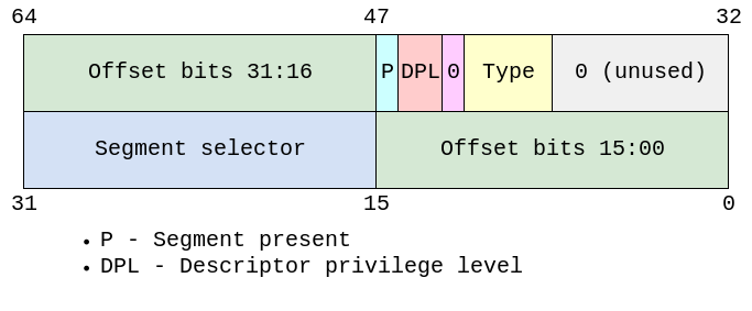
The main part of the descriptor is offset - essentially a pointer to an ISR within code segment chosen by segment selector. The latter consists of an index in GDT table, table indicator (GDT or LDT) and Request Privilege Level (RPL). For interrupt gates, selectors are always for Kernel code segment in GDT, that is it’s 0x08 for first GDT entry (each is 8 byte) with 0 RPL and 0 for GDT.
Type specifies gate type - task, trap or interrupt. For interrupt handler, we’ll use interrupt gate, because for interrupt gate CPU will clear IF flag as opposed to trap gate, and TSS won’t be used as opposed to task gate (we don’t have one yet).
So basically, you just fill the IDT with descriptors that differ only in offset, where you put the address of ISR function.
Interrupt service routines (ISR)
The main purpose of IDT is to store pointers to ISR that will be automatically
invoked by CPU on interrupt receive. The important thing here is that you can
NOT control invocation of an interrupt handler. Once you have configured IDT and
enabled interrupts (sti) CPU will eventually pass the control to your handler
after some behind the curtain work. That “behind the curtain work” is important
to know.
If an interrupt occurred in userspace (actually in a different privilege level), CPU does the following1:
- Temporarily saves (internally) the current contents of the SS, ESP, EFLAGS, CS and EIP registers.
- Loads the segment selector and the stack pointer for the new stack (that is, the stack for the privilege level being called) from the TSS into the SS and ESP registers and switches to the new stack.
- Pushes the temporarily saved SS, ESP, EFLAGS, CS, and EIP values for the interrupted procedure’s stack onto the new stack.
- Pushes an error code on the new stack (if appropriate).
- Loads the segment selector for the new code segment and the new instruction pointer (from the interrupt gate or trap gate) into the CS and EIP registers, respectively.
- If the call is through an interrupt gate, clears the IF flag in the EFLAGS register.
- Begins execution of the handler procedure at the new privilege level.
If an interrupt occurred in kernel space, CPU will not switch stacks, meaning
that in kernel space interrupt doesn’t have its own stack, instead, it uses the
stack of the interrupted procedure. On x64 it may lead to stack corruption
because of the red zone, that’s why kernel code must be compiled with
-mno-red-zone. I have a funny story about this.
When an interrupt occurs in kernel mode, CPU will:
- Push the current contents of the EFLAGS, CS, and EIP registers (in that order) on the stack.
- Push an error code (if appropriate) on the stack.
- Load the segment selector for the new code segment and the new instruction pointer (from the interrupt gate or trap gate) into the CS and EIP registers, respectively.
- Clear the IF flag in the EFLAGS, if the call is through an interrupt gate.
- Begin execution of the handler procedure.
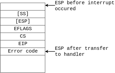
Note, that these 2 cases differ in what is pushed onto the stack. EFLAGS, CS and EIP is always pushed while interrupt in userspace mode will additionally push old SS and ESP.
This means that when interrupt handler begins it has the following stack:

Now, when the control is passed to the interrupt handler, what should it do?
Remember, that interrupt occurred in the middle of some code in userspace or even
kernelspace, so the first thing to do is to save the state of the interrupted
procedure before proceeding to interrupt handling. Procedure state is defined by
its registers, and there is a special instruction pusha that saves general
purpose registers onto the stack.
Next thing is to completely switch the environment for interrupt handler in the means of segment registers. CPU automatically switches CS, so interrupt handler must reload 4 data segment register DS, FS, ES and GS. And don’t forget to save and later restore the previous values.
After the state is saved and the environment is ready, interrupt handler should do its work whatever it is, but first and most important to do is to acknowledge interrupt by sending special EOI command to PIC.
Finally, after doing all its work there should be clean return from interrupt,
that will restore the state of interrupted procedure (restore data segment
registers, popa), enable interrupts (sti) that were disabled by CPU before
entering ISR (penultimate step of CPU work) and call iret.
Here is the basic ISR algorithm:
- Save the state of interrupted procedure
- Save previous data segment
- Reload data segment registers with kernel data descriptors
- Acknowledge interrupt by sending EOI to PIC
- Do the work
- Restore data segment
- Restore the state of interrupted procedure
- Enable interrupts
- Exit interrupt handler with
iret
Putting it all together
Now to complete the picture let’s see how keyboard press is handled:
- Setup interrupts:
- Create IDT table
- Set IDT entry #9 2 with interrupt gate pointing to keyboard ISR
- Load IDT address with
lidt - Send interrupt mask
0xfd(11111101) to PIC1 to unmask (enable) IRQ1 - Enable interrupts with
sti
- Human hits keyboard button
- Keyboard controller raises interrupt line IRQ1 in PIC1
- PIC checks if this line is not masked (it’s not) and send interrupt number 9 to CPU
- CPU checks if interrupts disabled by checking IF in EFLAGS (it’s not)
- (Assume that currently we’re executing in kernel mode)
- Push EFLAGS, CS, and EIP on the stack
- Push an error code from PIC (if appropriate) on the stack
- Look into IDT pointed by
idtrand fetch segment selector from IDT descriptor 9. - Check privilege levels and load segment selector and ISR address into the CS:EIP
- Clear IF flag because IDT entries are interrupt gates
- Pass control to ISR
- Receive interrupt in ISR:
- Disable interrupt with
cli(just in case) - Save interrupted procedure state with
pusha - Push current DS value on the stack
- Reload DS, ES, FS, GS from kernel data segment
- Disable interrupt with
- Acknowledge interrupt by sending EOI (
0x20) to master PIC (I/O port0x20) - Read keyboard status from keyboard controller (I/O port
0x64) - If status is 1 then read keycode from keyboard controller (I/O port
0x60) - Finally, print char via VGA buffer or send it to TTY
- Return from interrupt:
- Pop from stack and restore DS
- Restore interrupted procedure state with
popa - Enable interrupts with
sti iret
Note, that this happens every time you hit the keyboard key. And don’t forget that there are few dozens of other interrupts like clocks, network packets and such that is handled seamlessly without you even noticing that. Can you imagine how fast is your hardware? Can you imagine how well written your operating system is? Now think about it and give OS writers and hardware designers a good praise.